Kenwood TS-850S Hi-Fi RX/TX Mods
(Revision 1.4) by NU9N, W9AC, W5JAY and N3GX
(This
information courtesy of N3GX)
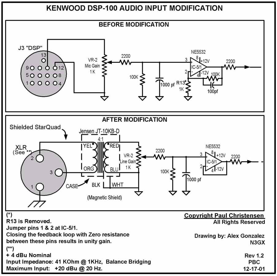
DSP-100 Direct Rack Audio Input Mod:
1) Remove the cover from the DSP-100 and face the front of the DSP-100
toward you.
2) Drill a hole in the rear of the DSP100 to
accommodate either an XLR or 1/4" TRS plug.
Orient
the hole just to the right of the power cord but to the left of the boundary
between the
Power supply and signal compartments.
3) Wire the transformer input to the jack you
just installed and place the transformer in
the far right corner of the power supply
compartment.
Make sure the transformer casing is
isolated from the chassis.
(Wrap electrical
tape around it if you prefer)
4) Locate the BLACK , WHITE and PINK wires
near the rear that goes into the Molex
connector.
5) Cut the PINK wire all the way to the right
of this connector.
(Leave about 1/4" of the wire on the
Molex)
6) Replace R13 with a 10k ohm resistor for +20dB of
gain.
Alternatively, unity gain can be achieved by
removing R13
and placing a wire jumper across IC-5's 100K feedback resistor
between pins 1 & 2.
7) Place a 1.2k ohm resistor to the PINK wire
that will be fed from the RED output wire
from the Jensen 4:1 transformer.
8) Combine the Black, White and Brown wires
from the Jensen Transformer and connect
them to a suitable SIGNAL ground inside
the DSP100.
The best location for this signal ground
is located directly in front of the center pin
of the Molex connector where the white
wire is connected.
There is a tiny little hole on the board,
and a soldier point just in front of this hole.
Refer to the schematic below for "Before/After" circuit modification
details:
DSP-100 Notes:
Do NOT remove the J3 DSP connector !
... It must stay to accommodate other connections in the circuit.
Set DSP-100 Rear Panel Dip Switches 1, 8 and 9
to OFF for full RX/TX Fidelity.
For AM operations using the DSP-100, Dip
Switch 1 MUST be set to the default ON
position for the front panel CARRIER LEVEL to be
operational.
For the best AM frequency response, do
NOT use the DSP-100. Use the Balanced Modulator instead. (See
mod below)
NOTE: If you will be doing both the Receiver and Balanced Modulator
mods, do the receiver mod first for easier access !
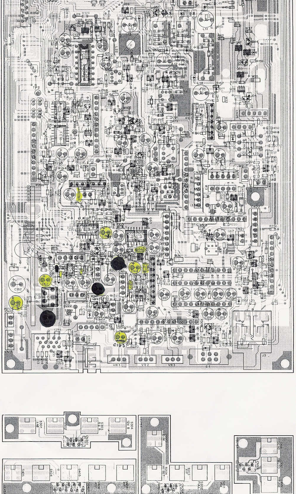
Kenwood TS-850S 20Hz ~ 6kHz Flat
Receiver Mods: (I.F. Board)
By Alex, N3GX
Notes before you begin:
If you will be changing ONLY
the three critical caps (indicated in RED),
then removal of the IF board is NOT necessary and the
caps can be bridged over the surface mounted caps 151,
156 and 161 on the top component side of the
board.
If you will be doing ALL
of the cap mods, remove all Molex connectors from the I.F. board located on
the bottom side of the chassis.
Remove all screws and completely remove the
board.
On the foil side of the board, make the
following additions: (Caps 151, 156 and 161 may be
placed on the top component side.)
Additional Notes:
- Leave the existing components and just add these caps
in parallel.
Note: If you will be completely replacing the
component, use electrolytic type
If you are simply bridging over the
capacitor in parallel, then tantalums ore ok
- The Three CRITICAL Caps are indicated in
RED and may be mounted
on the component side of the board so that removal
of the
I.F. board is NOT necessary!
- The rest are Optional
but will lower the final receiver frequency
response down to about 20Hz.
C151 .047uF to 1uF
(Tantalum)
C155 1uF to 10uF (Tantalum)
C156 .1uF to 1 uF (Tantalum)
C161 .1uF to 1uF (Tantalum)
(This cap was the biggest low frequency offender!)
C163 1uF to 10uF (Tantalum)
C164 1uF to 10uF (Tantalum)
C167 10uF to 47uF or 100uF (Electrolytic) (either value OK)
C170 0.1uF to 1 uF (Tantalum)
C172 0.1 uF to 1 uF (Tantalum)
C187 470 uF to 1000uF or greater (Electrolytic) This cap is in series
with the
speaker/headphones
CAPACITOR ORIENTATION:
C151 (+) lead toward the IC4 side.
C156 (-) lead to the base of Q27.
C161 (-) lead to the emitter of Q27
C170 (+) lead to R225
C172 (+) lead to IC7
See the attached X-ray trace for highlighted
location details.
Direct Balanced Modulator Input Mod for
AM without the DSP-100:
Note: If you will be doing the
"Flat Receiver" mod above, do this BEFORE
you do the Balanced Modulator mod! It's easier this way.
Balanced Modulator input:
Remove all Molex connectors and screws from the
IF board on the bottom of the 850. (This is the board that has the RTTY RCA
jack mounted to it)
Locate IC3 (It's a 7 pin single in-line IC) Pin
1 is located at the "Beveled" side of the IC chip.
Solder the RG-174 cable's center and shield to
the foil side of the board as follows:
Plus (Center of RG-174 Teflon RF Cable) to IC3,
Pin 1 on bottom of IF board.
Minus (Shield of RG-174 Teflon RF Cable) to IC3,
Pin 4 on bottom of IF board
Feed cable from IC3 under the chassis through a
corner hole of chassis to the top front left side.
There is a square hole that is clear from the
bottom to top of the chassis.
Coax Cable connections on the top front
left side to interface the RTTY RCA rear panel jack:
We need to disconnect the RTTY circuit and
replace it with the Line level audio from your rack to the balanced modulator
inputs performed above.
1) Orient the 850 so that the back is facing you.
2) Locate the small board on the top right side of rear chassis.
(This board mounts the RTTY, DSP 1 & DSP 2 RCA jacks)
3) Remove the Orange 2-wire (2-pin) green Molex connector. (White and Black
wires)
4) Remove the 1-pin (Orange) connector to the left of the 3-pin Molex
connector.
5) Solder the minus side of a 4.7uf Electrolytic capacitor to the 1 pin on
the mini board
6) Solder the Plus side of the 4.7uf Electrolytic capacitor to the center of
the RG-174 cable.
(This comes from IC4 pin 1 of the balanced modulator).
7) Solder the shield of the RG-174 to the far right pin (toward the outside
of the chassic)
of the 2 pin Molex connector that was there. (Where the Black wire was)
(This comes from pin 4 of the IC3 balanced modulator and is signal
ground).
The RTTY RCA jack is now ready for direct audio to feed the balanced
modulator.
It has been suggested by Jay - W5JAY, that an
18dB resistor T-pad be incorporated to properly drive the balanced modulator.
(See below)
If you want to build an external isolation
transformer coupler, use a Jensen 1:1 (JT-11P-1) with the 18db pad and wire it
as follows:
I used a Radio shack small aluminum project box
and mounded a 1/4" TRS input and an RCA output jack. The diagram below shows XLR
and RCA connections.
Notes:
The Resistor T-Pad network section provides 18dB
of attenuation. There are two 460 ohm resistors in series and a 150 ohm
resistor to ground between them.
(Thanks to W5JAY for this info!)
Upon request, Jensen will provide the 620pf
capacitor with the JT-11P-1 transformer.
For TRS 1/4" wiring: Tip is Plus, Ring is Minus
and Sleeve is Ground.)
A Radio Shack aluminum project box (Cat No
270-235) may be used to house the transformer and pad circuits.
Kenwood TS-850 I.F. TX Bandwidth
Power-On Menu Settings:
1) With the 850 turned off, press and hold the "SCAN" and
the right "M.Ch" buttons
simultaneously while tuning on the radio.
2) Select menu 1 by rotating the "M.CH/VFO.CH"
knob.
3) Turn the option to "ON" by
pressing the "UP" button.
4) Press the "CLR" button to
exit the power-on menu.
5) On transmit, you can now select the following
filters in the 8.83MHz i.f. resulting
in the following on-air bandwidths (with the
DSP-100):
None = 6kHz TX bandwidth (with DSP-100)
6k = 5kHz TX bandwidth
2.7k = 2.4kHz TX bandwidth